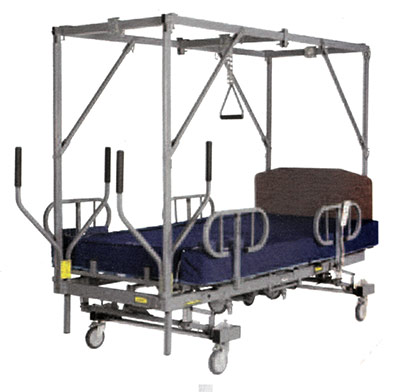
burke baribed
  • Product Overview
  • Operational Instructions
  • Downloads
  • Technical Specifications

The Bari 1000 is a unique healthcare patient support system providing dual width capabilities for safe bed transport. Created specifically to accommodate large and extra tall patients, all in one easy-to-use design, the Baribed 1000 offers multiple support functions to both the patient and the caregiver.

VENTURI 400 NPWT
3beds
2 Patient Surface Widths in One Frame
39" Width Extending to 48"
  3 Piece Interchangeable Width Mattress with Detachable Side Bolsters.   Exit / Enter at Foot of Bed Option to Exit at the Foot End.
         
f1   f2   f3
Length adjustable, reinforced
triangle positioning bar
  Great strength, easy adjustment position adjustable traction fixtures.   Heavy duty 6" x 1 1/4" steer
and lock casters.

1000 lb. Capacity - Static & Transfer. The Baribed 1000 provides smooth, safe transport of patients up to and including 1000 lbs. Designed specifically for the maximum in stability and safety, providing dependable support to both patient and staff.

Full Frame Trapeze Option accompanies the patient on the Baribed 1000 during transfers from one location to another providing solid, no bend-and-sway support for complete peace of mind. This unique trapeze system provides an enhanced, strength enriched frame to ensure confidence use, safety and maximum stability.

State-of-the-art Low Voltage Actuator System. Hospital grade plug providing low/high efficiency and low power consumption at 1.6 amps.

  KEY PRODUCT FEATURES:
  • Trendelenburg / Reverse Tendelenberg
  • Hi-Lo: 28" to 14"
  • Cardiac Lounge / Chair Positioning
  • Integrated Scale System measures patient weight in lbs. and kgs. with accuracy of 0.2% +/- 1 digital reading
  • Compact "Fold and Roll" 1 person delivery system
  • 2 Widths in 1 Frame 39" width extending to 48"
  • Full Frame Trapeze fully adjustable, maximum support
  • Battery Back-up No hand cranks to lose
  • CPR Release Mechanism
  • Adjustable, powder coated half side rails telescoping to 6"
  • 1 Wand Finger tip Control
  • Oak Finish headboard and foot board
  • Easy Patient Egress - In and Out of the foot of the bed with the Dual Passage Assist Option.
  IMPORTANT SAFETY INFORMATION
  • All persons with access to the bed must read the Owner's Manual before using the bed. Failure to do so could result in improper use which could damage the bed or injure persons.
  • 1000 lb. patient use weight limit. Use of bed with persons above this weight may cause damage to bed and persons.
  • To transport a patient to bed, the bed high/low must be in it's lowest position with the frame resting on the transverse caster bars. Failure to do so could result in compromising the structural integrity and stability of the bed which could damage the bed or injure persons.
  • Possible fire hazard exists when bed is used with oxygen administering equipment other than a nasal mask or 1/2 bed length tent. Oxygen tents should not extend below the mattress support level.
  • The electronics are not designed to be used in environments containing flammable anesthetics. Possible fire hazard exists.
  • Keep the side rails in a raised position while patient is on the bed to prevent patient from accidentally falling off the bed.
  • If patient restraints are used, they must be attached to some point on the bed that articulates when the gatches are raised and lowered. Failure to do so could result in the restraints injuring the patient.
  • Keep the power cord plugged into a wall outlet.
  • CAUTION: Run the cord under the bed frame and positioned so as to prevent being walked on or rolled over by the bed casters.
  • Elevating the head gatch facilitates easier breathing for heavier patients. Consult a doctor.
  • If needed, orthopedic equipment can be attached to the bed.
  • CAUTION: hang the hand control pendant on the side rail when not in use. Run the cord under the bed frame and keep it clear of moving parts to prevent possible damage to the cord.
  • CAUTION: When the bed is in use, the casters must be positioned so that the locking tabs are locked and pointed towards the foot end of the bed. Failure to do so will cause damage to the bed.
  • Keep the head of the bed a minimum of 4" from walls to avoid contacting a wall when running the hi-low. Failure to do so could result in damage in the bed and/or the wall.
 
  ASSEMBLY / DISASSEMBLY INSTRUCTIONS
  • Set the head and foot boards aside to be assembled later.
  • WARNING: Lock the four transport casters to prevent the bed from moving when you unfold the head and foot sections as movement can cause injury.
  • Remove the "L" shaped foot end transport latch located on the transport pole.
  • Gently lower the foot end section of the bed. WARNING: If the foot end or head end of the bed is allowed to drop while being lowered, injury to persons and/or damage to the bed could occur.
  • Make sure that the black woven safety strap located at the head end of the bed is securing the head gatch patient support surface to the base. WARNING: Unexpected movement of the patient support surface and possible injury could occur if the safety strap is not in place.
  • Remove the head end transport latch bracket located on the transport pole placed vertically in the center of the bed.
  • Gently lower the head section of the bed. WARNING: If the foot end or head end of the bed is allowed to drop while being lowered, injury to the person and/or damage to the bed could occur.
  • Release the black woven safety strap located at the head end of the bed and the remove 3/4" wrench.
  • Slide a center anti-pivot locking bar into position and pin it. One end of the bar must be pinned in place and the opposite end must be anchored through a side bracket by means of a bolt and square washer. Tighten the bolt firmly with the 3/4" wrench.
  • Repeat the installation process on the opposite side of the bed. WARNING: Failure to properly install the center anti-pivot locking bars could result in injury to persons and/or damage to the bed.
  • IMPORTANT: Loosen the four "jack bolts" used to protect the scale system load cells during storage and transport. Turn the bolts counterclockwise until they spin freely. Failure to loosen jack bolts will cause the scale system measurements to be inconsistent!
  • Store the 3/4" wrench in Velcro holder with black safety strap.
  • CAUTION: Position and lock the four casters (located at the corners off the bed) with locking tabs facing the foot end of bed. Failure to do so will result in damage to the casters during hi-low use.
  • Plug bed power supply into an AC outlet.
  • Raise bed hi-low approx. 5 inches to take weight off of the center transport wheels.
  • Remove the pull pin securing central transport system, pivot the system inward and up. Lock the transport system "up out of the way" with the pull pin holder under the head gatch.
  • Raise the head gatch and store the central transport pole in it's holder under the head gatch.
  • Lower the Hi-low system.
  • Position the hinged mattress support tabs as required to accommodate various mattress widths.
  • Install mattress system.
  • Install head and foot boards into square tubes at the ends of the bed.
  • Hang the scale readout assembly on the foot board and connect the cable.
 
  OPERATIONAL INSTRUCTIONS

The Baribed 1000 operates from a low voltage power supply with a battery back up. If the patient must change position while being transported or in the event of a power failure, the batter backup will support several position changes to maintain patient comfort.

Trendelenburg FUNCTION: The Trendelenburg function is controlled by the same buttons in the hand control as the hi-low function.

To access the Trendelenburg position lower the hi-lo to the lowest position than flip the Trendelenburg switch on the ON position. Next raise the foot end with the hi-lo button on the hand control.

To access the reverse Trendelenburg position raise the hi-lo to the highest position than flip the Trendelenburg switch to the ON position. Next lower the foot end with the hi-lo button on the hand control.

BED ELEVATION (HI-LO): Press and hold the bottom UP or Down buttons on the hand pendant to raise or lower the bed as desired.

FOOT (UP-DOWN): Press and hold the middle UP or Down on the hand pendant to raise or lower the foot as desired.

HEAD ELEVATION: Press and hold the top UP or Down buttons on the hand pendant to raise or lower the head of the bed as desired. Maximum head elevation is 60 degrees.

I.V. POLES: If needed, I.V. support poles can be attached to each corner of the bed base frame.

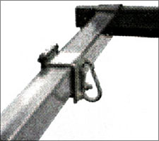
  • You must insert the side rail support frame into the horizontal tube under the bed until it contacts the stop pin.
  • Retract the stop pin by hand until you can pass the arm at least 4" into the bed frame.
  • Release the stop in and continue to insert the support frame to the desired width.
  • Tighten the adjustable knob until it firmly engages the side rail bracket.
  • To adjust the width, loosen the black knob under the bottom of the side rail, slide the horizontal telescoping tube in or out to the desired position and tighten the knob.
  • Loosen the black knob until the arms moves freely.
  • Slowly pull the frame out until fully engages the stop pin.
  • Manually retract the stop pin and continue to remove the arm.
  • Normally, the side rail support frame should not be completely removed for anything other than setup or maintenance.

WARNING: Failure to properly insert the arm past the stop pin will cause the arm to be improperly installed possibly resulting in serious injury or death.
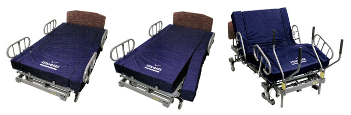
  • Loosen the black clamp know opposite the spring loaded pull pin.
  • Hold the side rail with one hand and pull on the pin to release the side rail.
  • Allow the side rail to slide down out of the way until the bottom of the support tube engages the floor.

  • Make sure the black knob opposite the spring loaded pull pin is loose.
  • Lift the side rail until the spring loaded pull pin completely re-engages one of the preset hole positions.
  • Tighten the black knob located on the opposite side of the spring loaded pull pin. Side rails must be in the up position to move the bed.

  • Grasp the side rail with one hand while loosening the black clamp knob.
  • Retract the spring loaded pull pin and lift out completely vertically to the gatch.
 
  CPR PROCEDURES
  • Lower the head gatch to approximately 45 degrees by using the head down pendent control.
  • Once the head is lowered to approximately 45 degrees, you may use the emergency CPR release on the head gatch.
  • The emergency CPR release can be used to lower the patient faster than running the actuator the rest of the way down.
 
  PATIENT TRANSFERS
  • Set the brake on all casters with spring locking lever pointing towards the foot end of the bed.
  • Adjust the height of the bed to match transfer height (it is best to always transfer down).
  • Lower the side rails or remove them.
  • Use a hospital sheet and appropriate number of personnel to lift the patient on/off the bed.
 
  TRANSPORTING THE BED AND THE PATIENT
  • WARNING - Maximum patient weight in bed for transport is 1000 lbs. Transporting a patient above 1000 lb. can damage the bed and injure the persons.
  • WARNING - The bed hi-lo must be in the lowest position to prevent damage to the bed and provide the maximum stability.
  • WARNING - Side rails must be in the highest position to prevent patient from falling out of bed.
  • CAUTION - Check the bed width and side rail adjustment for doorway clearance to prevent damage to the bed and door frames.
  • Unplug the bed AC power cord and scale system power cords, wrap the AC power cord around cord holder.
  • Unlock the two head end caster locks and one foot end caster lock. This will leave you with one directional lock caster engaged to assist in transport down a hall.
  • Use a minimum of two persons to transport the patient. WARNING: Moving bed down inclines or dropping off a ledge (such as moving into an elevator or across a threshold) can result in damage to bed and injury to persons.
 
  PATIENT TRANSFERS
  • Set the brake on all casters with spring locking lever pointing towards the foot end of the bed.
  • Adjust the height of the bed to match transfer height (it is best to always transfer down).
  • Lower the side rails or remove them.
  • Use a hospital sheet and appropriate number of personnel to lift the patient on/off the bed.
 
  Links to Online Videos (You Tube) and Demonstrations
video Bariatric Bed Training Basics

training

  AVAILABLE LITERATURE
AME3000Sell Sheet BARI 1000 Sell Sheet BARI 1000 Sell Sheet CLICK HERE
AME3000Sell Sheet BARI 1000 Brochure CLICK HERE
Click here to download Adobe Acrobat Reader.
  TECHNICAL SPECIFICATIONS

Platform Dimensions:

  • 39" Width x 84 Length

Frame:

  • 92 1/2" Long
  • 41 1/2" Wide Caster to Caster
  • 42 1/2" Wide Side Rail to Side Rail
  • 42 1/2" Wide with Scales
  • Deck High: 28"
  • Deck Low: 14"

Miscellaneous:

  • Class fully electric: Modular electronics Pkg. Approved to UL, CSA & CE Standards
  • Capacity: 1000 lbs.
  • Maximum angle of head gatch elevation: 60 degrees
  • Maximum angle of upper foot gatch elevation: 24 degrees
  • Maximum angle of lower foot gatch elevation: 26 degrees
© American Medical Equipment - 2013. All Rights Reserved.