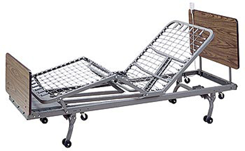
| Assembly Instructions |
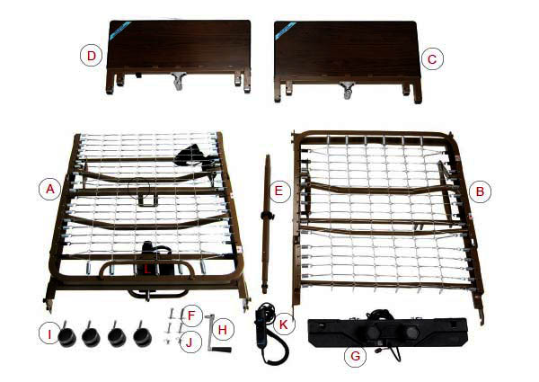 1. Confirm that all parts are present. 1. Confirm that all parts are present. |
A. Foot Spring
B. Head Spring
C. Head Board
D. Foot Board
E. Hi/Low Shaft
F. Locking Pins
|
G. Motor
H. Hand Crank (attached to foot board for shipping)
I. Casters (4) - 2 locking, 2 non-locking
J. Spring Clips (2)
K. Hand Pendant
L. Full Electric Motor |
| 2. Connect the head spring by aligning with foot spring and swinging both ends away from each other. |
| |
 |
3. Optional: Insert lock pin through connected sleep surface and secure with spring clip. 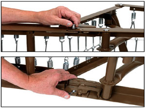 |
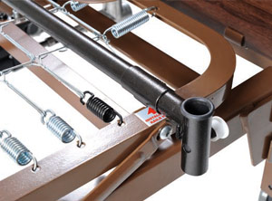
4. Place the foot spring standing up on the floor on its side. Slide Hi/Low shaft through hanger bracket.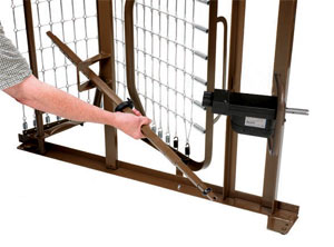 |
5. Install Hi/Low shaft to the Hi/Low motor at the foot section of the bed by inserting the spring loaded side
of the shaft to the bottom receptacle as shown.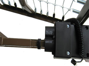 |
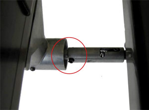
6. Slide lock collar 1/4” from the foot side of the hanger bracket as shown.
Tighten thumb screw.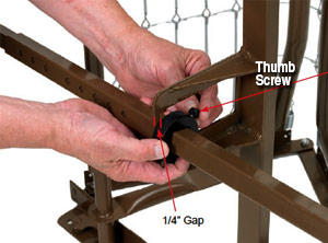 |
7. Hi/Low shaft connected to Hi/Low motor.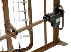 |
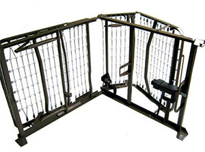
8. Connect head section and foot section by squeezing together and attaching with spring links. Pull up the head section and foot section to release tension between the springs. |
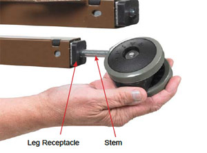
| 9. Install the casters by inserting the stem of the caster into the leg receptacle. It is recommended to install 1 locking caster and 1 non- locking caster on each bed end. The locking casters should be installed diagonally from each other. |
 |
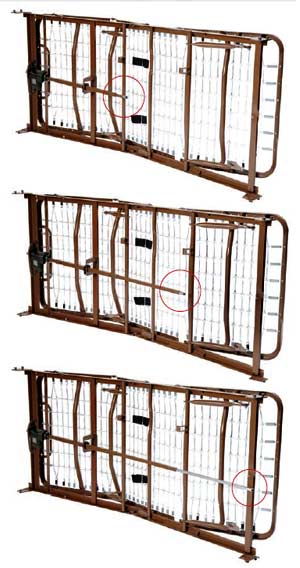
10. With bed on side extend the shaft until it reaches the full length of bed.
A. NOTE: The shaft adjustment holes are marked to indicate the style (semi/full) of bed the shaft is being installed on. |
 |
11. Attach the head board and foot board as shown.
A. NOTE: The head section is higher than the foot section. However, they are interchangeable with each other, with all other Drive and other manufacturers head and foot boards. |
 |
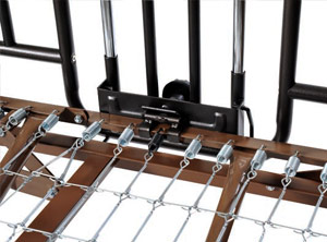
12. Install the head end of
the shaft as shown. 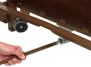 |
13. Release the spring loaded shaft on the hi/low motor and insert the shaft into the gear box on the footboard.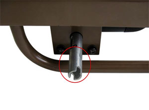 |
| 14. Make sure the slot on the spring loaded shaft engages the roll pin on the gear box. |
 |
| |
| |
| Motor Installation |
HAND CONTROL
The Competitor bed comes with a hand control that will illuminate when the bed is plugged into a grounded or polarized wall outlet, or with 9V battery (sold separately) installed in the hand control. The hand control will illuminate as long as the wall or battery has power. With this battery installed, the motor can be operated to return the sleep surface to the horizontal position in the event of
a power failure. |
 |
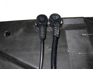
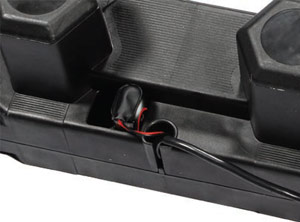
| NOTE: Before installing motor, plug hand pendant and Hi/Low motor cable into motor as shown |
 |
1. Connect the 9V battery (sold separately) to the
battery clip on the motor. It is stored in the recess
under the motor cover. With this battery installed,
the motor can be operated in the event of a power
failure. |
 |
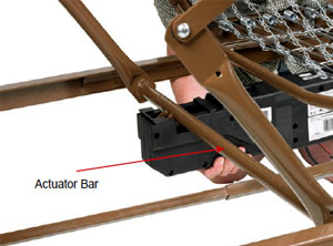
| 2. Align the motor with the actuator bar and lift the head spring to the highest position. The motor will automatically be pulled towards the bed and lock onto the accuator. Repeat for foot section. |
 |
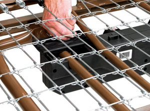
| 3. After the motor is installed, slide locking covers back on motor. |
 |
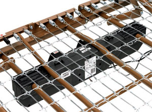
| 4. Final placement. |
 |
| |
| |
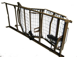
| Bed Rail Installation |
| Attaching Bed Rails |
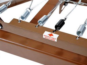 |
Half Rails
The head section features labels on the frame marked, “Attach Half Rails Here” and black springs for proper placement. |
 |
Full Rails
• The foot and head section have color coded springs, labels and notches in the frame.
• Install the cross brace between the black springs for proper rail placement. |
 |
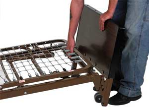
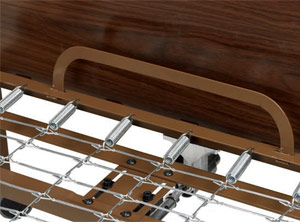
| Before a mattress is laid on the bed, flip up the mattress guard to reduce the movement of the mattress. |
 |
| |
| |
| Maintenance & Safety Checks |
|
Drive recommends the following maintenance and cleaning procedures be conducted between users.
ELECTRONICS
- Check all controls to make sure all functions work properly.
- Foot control
- Head control
- Hi/Lo
- Check all cables for damaged or frayed wires.
- Power cord
- Pendant cord
- Check to make sure all plugs are fully inserted or attached.
- Check 9V battery on motor and replace annually.
BED FRAME & SLEEPING SURFACE
- Visually check all welds.
- Head section
- Foot section
- Main Frame
- Check joints between sleeping surface sections for loose fasteners.
CLEANING
- The metal parts of the bed are covered with a powder coating. Clean all coated parts with mild detergent and warm water.
- Periodically raise head and feet sections of the bed and remove dust from frame. Also, periodically remove mattress and clean mattress deck.
LUBRICATION & MECHANICAL
- Lightly grease all actuator screw threads with white lithium grease.
- Lubricate all caster roller and swivel bearings with light machine oil.
- Check all bolts and tighten as needed.
|
| |
| |
|
|
|

|