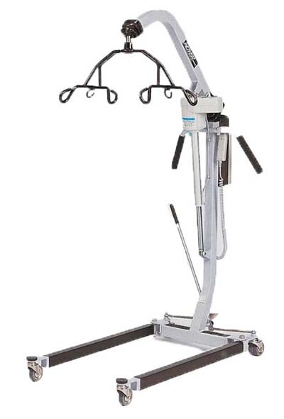
| ASSEMBLY |
| 1. |
The following tools are required for assembly:
- 3/4" & 1/2" wrench
- 3/16" hex wrench
- 1/8" hex wrench
- thin layer of grease should be applied to all bolts.
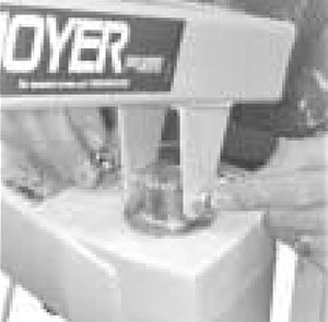
- Carefully unpack Hoyer Lifter. Check for 6-point cradle and adjusting lever handle.
- Insert mast in base and tighten bolt.
|
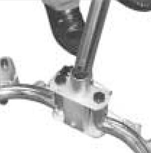 |
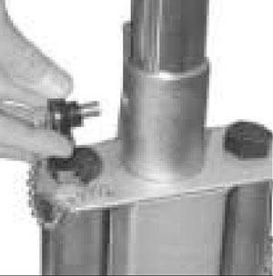
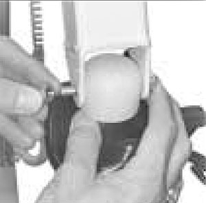
| 2. |
- Make certain boom points in same direction as
base legs. Thread mast safety lock and stud into
threaded hole in mast sleeve. Tighten firmly,
locking mast into base. Keep mast and
base locked at all times except when removing
mast from base for storage.
|
 |
| 3. |
- Attach boom to top of mast with
hardware
|
 |
| 4. |
- Attach the actuator to the mast and the motor end to the boom with hardware.
|
 |
| 5. |
- Cradle Attachment
- Remove nut and bolt from cradle.
- Hold cradle in position at the end of the boom and align the holes of the pin and cap with the holes in the boom end fork.
- Attach cradle with hardware.
- Swivel cradle to check for free movement.
- Pull vinyl boot over connection, making sure middle rib is over hardware).
|
 |
| 6. |
- Attach the power unit control box to bracket on
back of mast. Attach battery pack to control box
and bracket.
- Route actuator cable along mast and secure with clips provided. Make sure to leave approximately 8 inches of cable prior to the top clip to allow for maximum lifter articulation).
- Plug cords in proper outlets, pressing firmly into place
|
|
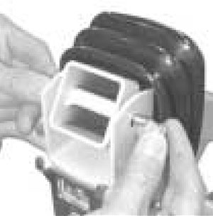
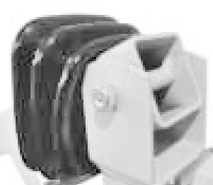
| 7. |
- Raise boom to highest position; pull vinyl boot over bolted connection
|
 |
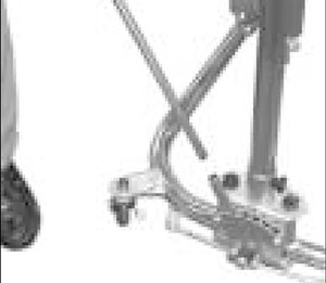
| |
- Attach adjusting lever handle into base Wheel locks are provided for parking. To lock casters, step on cam lever on side of casters. To unlock, step on highest cam lever
|
 |
| |
| |
| OPERATION |
A. HAND CONTROL
The hand control activates the lifter and has two buttons; one “up” and one “down”.
Simply press the button for the direction you want the lifter to move.
B. BATTERY CHARGING
Plug the charger into the wall socket (110 V) prior to connecting the plug to the control box. If the unit sits idle for an extended period of time, the battery life diminishes. A control box with battery.
should be charged at least every six months. However, the longest life is obtained when the battery is fully charged. After approximately 6 hours of charging, the batteries will be fully charged.
NOTE– It is not possible to overcharge batteries. (Battery is a Gel Cell).
NOTE– Battery alarm will go off when battery is low.
C. USER INSTRUCTIONS
The duty cycle printed on the label of the control box must always be noted. If this is exceeded, the control box could overheat and become damaged. Unless otherwise specified on the label, the duty cycle maximum is 10% or 6 min/hour of continuous operation. To widen or narrow the base, pull adjustment handle back to unlock. Handle can be moved to the right to widen the base or to the left to narrow the base. |
|
| |
|
|

|