| OPERATOR CONTROL PANEL |
 |
| 1. |
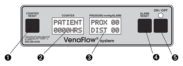
COUNTER RESET
- Resets counter back to zero.
|
| 2. |
COUNTER DISPLAY
- Displays length of time unit is in operation in addition to pressure alarms.
|
| 3. |
PRESSURE DISPLAY
- Displays settle distal and proximal pressures in addition to alarm instructions.
|
| 4. |
ALARM RESET
- Resets alarm after activation.
|
| 5. |
POWER SWITCH
- Sets power ON or OFF. Green light will illuminate when ON.
|
|
|
| APPLICATION |
| 1. |
Prepare air pump and cuff(s)
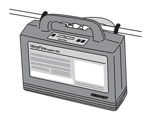
- Hang pump from bed frame (foot of bed), bed rail, or rest on floor or table with handle facing upright. Connect power cord to a 115V AC — 60 Hz power source.
- For patients with a small calf or thigh, trim Calf Cuff or Thigh Cuff.
|
 |
| 2. |
Apply cuff(s)
- All cuffs are hypoallergenic and may be placed directly against the skin or over a light compression dressing.
-
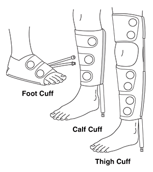
Foot Cuff - Apply cuff with the air cell centered on bottom of foot and with tubes on left.
Calf Cuff - Apply cuff with the air cell centered on back of leg and with tubes toward foot.
Thigh Cuff - Apply cuff with the air cells centered on back of calf and thigh and with tubes toward foot.
- All cuffs are hypoallergenic and may be placed directly against the skin or over a light compression dressing.
- When using the Calf Cuff and Thigh Cuff, the position of the air cell on the calf and/or thigh does not significantly affect venous velocity, or the sequential performance of the system.
|
 |
| 3. |
Connect System
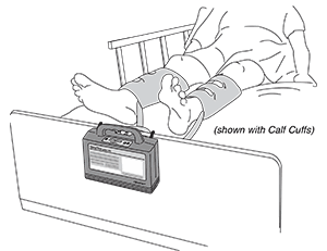
- Attach the tube assembly to cuffs and pump. Turn on pump to activate system.
- Attach the tube assembly to cuffs and pump. Turn on pump to activate system.
|
 |
|
|
| OPERATIONAL FUNCTIONAL TEST |
To obtain accurate readings, allow the pump to cycle for five minutes before beginning “Optional Functional Test” (peak pressures gradually rise through the first five cycles).
The Aircast VenaFlow system is maintenance-free. The “Optional Functional Test” is for verification only, and not required before use. |
| 1. |
Visual Test: Inspect pump case, handle, hooks, connectors, and power cord for damage. |
| 2. |
Pressure Verification Test (requires Pressure Verification Kit, P/N 3004): Verify normal operation and correct pressure by following instructions included with the Aircast Pressure Verification Kit (P/N 3004). |
| 3. |
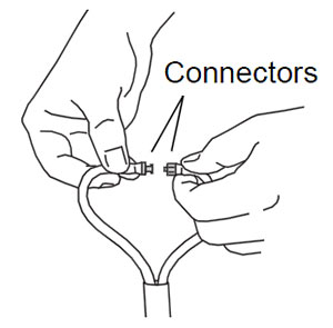
Alarm Verification Test: Attach tube assembly to pump and connect power cord to 115V AC — 60 Hz power source. Simulate a kinked tube situation by firmly securing the male and female connectors together at both ends of the tube assembly. If only one end of the tube assembly is connected the kink alarm will not activate. Turn on pump to activate system. Under proper conditions, during the first cycle, the pressure display should indicate proximal and distal pressures greater than 40 mmHg. Due to the simulated “kink”, the second cycle should activate an audible alarm with the display reading “TUBE ALARM”, “CHECK FOR” “KINKED TUBES”. |
 |
| 4. |
Electrical Safety Test:
Perform electrical safety check in accordance with UL 2601 guidelines or your institution’s standards. |
If the unit fails any of these tests, return to Aircast for prompt repairs or replacement.
Do not attempt to service unit. If pump is removed from case, unit will be ungrounded. |
|
|
| OPERATION |
| |
When the system is turned on, the pump is activated and begins to pressurize. When target pressure is achieved, the system begins a cycle and inflates the cuff air cells. The distal air cell inflates first with the proximal air cell inflating .3 seconds later. After 6 seconds of compression, the air cells deflate and the pressure display illuminates the distal and proximal pressures for fifty-four seconds. The pressure display is updated after every cycle. Pres-sure and inflate/deflate cycles are automatic and unit will activate an alarm if the system is not functioning properly (see Top Panel Displays / Alarms). |

|