|
 |
- Product Overview
- Operational Instructions
- Downloads
- Technical Specifications
|
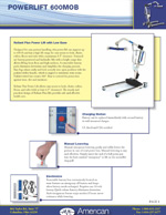
Designed for easy patient handling, this power lift can support up to 450 lb and has a high lift range for easy access to beds, chairs, toilets, floors and tubs with a maximum 4.5” clearance. Featured are battery-powered and hydraulic lifts with a height range that allows lifting from floor and high surfaces. A removable battery pack eliminates downtime and simplifies the charging process. Base legs adjust easily and lock securely into open position with the padded shifter handle, which is angled to minimize wrist strain. Padded swivel bar rotates 360°. Base is covered for protection against wear, dirt and moisture.
Powerlift 600 MOB allows easy access to beds, chairs, toilets, floors, and tubs (with at least 4.5" clearance). The sturdy and practical design of the Powerlift 600MOB provides safe and effective health care.
|
 |
 |
|
 |
|
 |
|
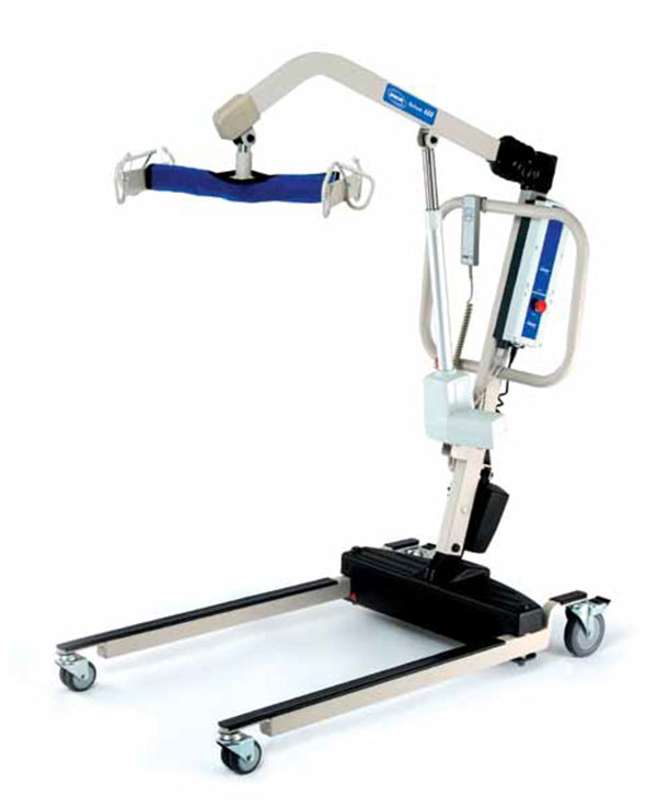
Manual emergency lowering gently and safely lowers the patient in case of total power loss. Manual lowering is easy and effortless. Simply insert the end of a ball point pen into the hole marked “emergency” or lift on the accessible ring-pull |
|
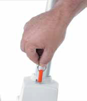
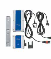
Battery can be replaced immediately with second battery in wall-mounted charger.
UL listed and CSA certified |
|
Removable battery box conveniently located on mast features an emergency off button and beeps when battery needs recharged. Requires one 24-volt battery Quick-release battery eliminates downtime Anti-entrapment feature stops motion if boom meets resistance while lowering |
|
| KEY PRODUCT FEATURES |
- Base legs adjust easily and lock securely into open position
- Total pinch-point protection covers all moving parts for added safety
- Covered base provides protection against wear, dirt and moisture
- Height range allows lifting from floor and high surfaces
- Padded swivel bar with 360 degrees rotation and six-point hookup
|
|
| ASSEMBLY |
| 1. |
Unpack the components from the shipping carton.
DO NOT remove the plastic wrap that secures the boom to the mast |
 |
| 2. |
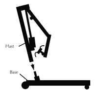
Assembling the Mast to the Base
1. If locking-type casters are on the patient lift, lock them.
2. Remove the shoulder bolt, nut and washer, that secures the mast
in the U-shape cut-out of the base.
3. Position the mast in an upright position and place the mast into the
U-shaped cut-out of the base.
4. Insert shoulder bolt with washers through the base and mast.
5. Secure with nut. |
 |
| 3. |
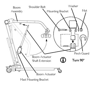
Assembling the Boom Actuator
1. Remove the shoulder bolt, washer and nut from the mounting bracket on the boom assembly.
2. Unpack the pinch guard from the patient lift carton.
3. Cut the plastic-wrap that secures the boom and mast together.
4. Lift-up on the boom and place it on your left shoulder.
5. Let the boom actuator rest on your shoulder and rotate the shaft extension of the actuator assembly until it lines-up with the mounting holes in the boom assembly.
6. Place the pinch guard over the shaft extension of the boom actuator.
7. Align the holes of the boom assembly mounting bracket with those of the boom actuator and insert the bolt. Secure with nut.
CAUTION
DO NOT over-tighten the nut and bolt. This damages
the mounting bracket.
The bottom of the boom actuator assembly will already be assembled to the mast mounting bracket.
Be sure that the bolt is completely through the holes of the boom assembly mounting bracket and the actuator assembly. The boom assembly will pivot easily if the mounting hardware is aligned properly |
 |
| 4. |
Installing the Leg Actuator to the Base
1. Slide the leg actuator into the slot in the base of the patient lift (Detail B).
2. Perform the following to secure the leg actuator to the pivot bracket (Detail A):
A. Turn the patient lift on its side.
B. Position slot in leg actuator over the pivot bracket.
C. Install the pin through the leg actuator and pivot bracket and
secure with hitch pin.
D. Return the patient lift to the upright position.
3. Perform the following to secure the leg actuator to the mast bracket:
A. Position leg actuator between mast brackets.
B. Move the legs to align the holes in the leg actuator with the holes in the mast bracket.
C. Install the pin through the holes of the leg actuator and mast bracket and secure with hitch pin.
4. Plug the pendant control (not shown) into the bottom of the control box. |
 |
| 5. |
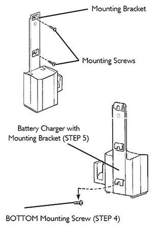
Mounting the Battery Charger
1. Place the battery charger with mounting bracket on the wall at the desired position.
2. With a pencil, mark the middle hole position.
3. Measure down 6½ inches from the pencil mark and drill one mounting hole.
4. Install the bottom mounting screw until there is an approximate 1/8-inch gap between the screw head and the wall.
5. Install the battery charger with mounting bracket onto the bottom mounting screw.
6. Drill the remaining two mounting holes.
7. Install the two remaining mounting screws through the mounting bracket and into the wall. Tighten securely.
8. Plug the battery charger into the wall electrical outlet.
9. Verify that ON is illuminated. |
 |
|
| OPERATING INSTRUCTIONS |
| 1. |
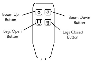
Raising/Lowering the Boom
To raise the patient lift, press the boom up button (up arrow) to raise the boom and the patient.
To lower the patient lift, press the boom down button (down arrow) to lower the boom and the patient.
To open the legs, press the legs open button.
To close the legs, press the legs closed button.
|
 |
| 2. |
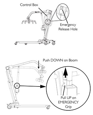
Activating a Mechanical Emergency Release
To activate the primary emergency release, insert a pen into the hole labeled “emergency” on the control box of the lift and push down on the boom at the same time.
All lift actuators are equipped with a mechanical Emergency release. The mechanical release will enable the actuator to retract without power. The actuator will only retract while under load and the mechanical
Emergency release is pulled. The release is colored reddish orange with the word Emergency spelled out in white.
In cases where the primary release is either not functioning or unreachable, a secondary emergency release may be used. To activate the secondary release, pull up on the EMERGENCY grip and push down on the boom at the same time.
|
 |
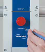
| 3. |
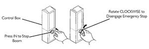
Performing an Emergency Stop
Press the RED/ORANGE emergency button on the control box in to stop the boom assembly and patient from raising or lowering.
Rotate the RED/ORANGE emergency stop button clockwise to disengage the emergency stop. |
 |
| 4. |
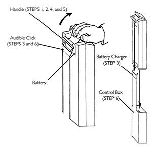
Charging the Battery
1. Lift up on the handle on the back of the battery.
2. Lift the battery up and out away from the control box.
3. Place the battery on the battery charger as shown. Make sure there is an audible click.
4. Lift up on the handle on the back of the battery.
5. Lift the battery up and out away from the battery charger.
6. Reinstall the battery onto the control box as shown. Make sure there is an audible click. |
 |
|
| LIFTING THE PATIENT |
 |
| 1. |
Positioning the Patient Lift
1. Press the legs open button on the pendant to open the legs of the patient lift to maximum.
2. Position the patient lift using the steering handle.
3. Press the boom down button on the pendant to lower the boom for easy attachment of the sling. |
| 2. |
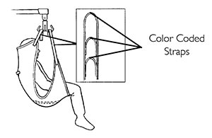
Attaching a Sling
1. Place the straps of the sling over hooks of the swivel bar.
2. Match the corresponding colors on each side of the sling for an even lift of the patient. |
 |
| 3. |
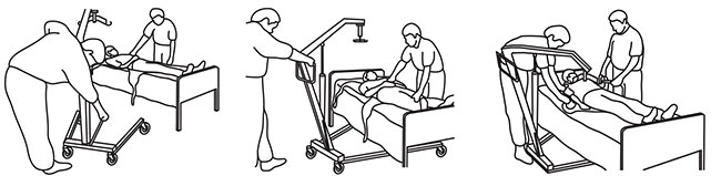
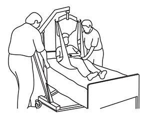
Lifting/Moving the Patient
1. Press the boom UP () button to raise the patient high enough to clear the bed. The patient’s weight will be fully supported by the patient lift.
2. Place patient’s arms inside of sling.
3. Swing the patient’s feet off the bed when the patient is clear of the bed surface.
4. Move the patient lift away from the bed using the steering handle.
5. Turn the patient so that he/she faces assistant operating the patient lift when moving the patient lift away from the bed.
6. Press the boom DOWN button to lower the patient until his legs straddle the mast and his feet rest on the base of the patient lift.
7. Pull the patient lift away from the bed and then push it from behind with both hands firmly on the steering handle. |
 |
| 4. |
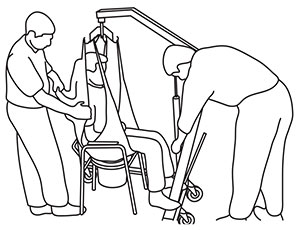
Transferring to a Commode Chair
1. Lift the patient from the bed.
2. Press the boom up button to elevate the patient high enough to clear the arms of the commode chair. Their weight will be supported by the patient lift.
3. Guide the patient onto the commode chair. This may require two assistants.
4. Press the boom down button to lower the patient onto the commode chair leaving the sling attached to the swivel bar hooks.
5. When complete, recheck the sling for correct attachments.
6. Press the boom up button to raise the patient off the commode chair.
7. When the patient is clear of the commode surface (using the steering handles), move the patient lift away from the commode chair.
8. To return the patient to bed, reverse the steps in Lifting the Patient.
9. To return or place the patient in a wheelchair, |
 |

|
| Overall Height |
24" - 74" |
| Clearance |
4.5" |
| Base Length |
48" |
| Base Width |
Open: 41", Closed: 26.5" |
| Caster Options |
Front: 3", Rear: 5" |
| Weight Capacity |
450 lbs. |
| Product Weight |
106 lbs. |
| Battery |
24 V Rechargeable Sealed |
| Charger |
Output: 24 DC |
| Power |
Audible Low Battery Alarm |
| Lift Per Charge |
150 - 300 |
|
|