| 1. |
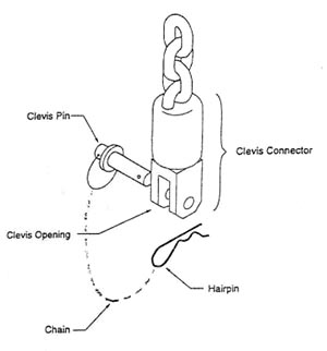
HARNESS ATTACHMENT
For Spreader Bar Style:
Remove the Hairpin from the Clevis Pin and remove the pin. Place the spreader bar in the Clevis opening so the Clevis Pin can pass through the hole in the center of the Spreader Bar then replace the Hairpin.
For the Hugger Style:
Remove the Hairpin from the Clevis Pin and remove the pin. Place the ring of the Hugger into the Clevis Opening so that Clevis Pin can pass through the ring, then replace The Hairpin.
|
 |
| 2. |
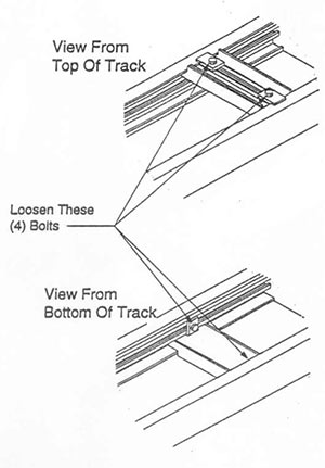
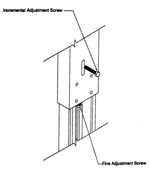
TRACK HEIGHT ADJUSTMENT
1. Secure The Hoist: Move the hoist to the
opposite end of the column being adjusted and
have a second person hold it in place while
height adjustment is made.
2. Adjust The Height: Loosen the Incremental
Adjustment Screw with a 9/16” wrench while
supporting the upper section with one hand.
Continue to loosen the screw to allow the
section to become unlocked and free to move.
Raise or lower the track to desired height but
not more than 6” at a time (93” max height of
track). Securely tighten the screw making sure
the holes are aligned.
3. Repeat the procedure: Repeat steps A & B to
adjust the opposite Column. Take care not to
raise or lower a Column more than 6” above
opposite Column. Repeat this cycle until
desired height is reached fro the track (93” max
height of track).
4. Level the track: Loosen one to two turns but do
not remove the Incremental Adjustment Screw.
Then using the Fine Adjustment Screw adjust
the height on one side to level the track
(clockwise rotation raises track). Securely
tighten both the Incremental Adjustment
Screws. |
 |
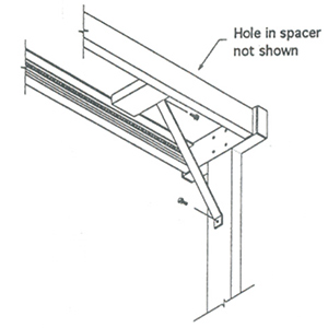
| 3. |
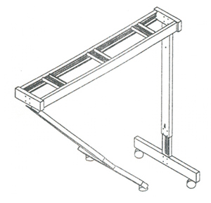
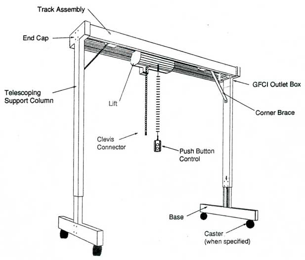
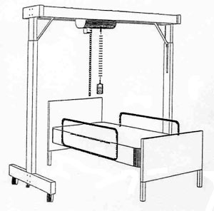
POSITIONING UNIT
Position the lift over the bed with the centerline of the lift over the midsection of the person to be
transferred. Also position the track offset so that sufficient space is provided to place the wheelchair
between the bed and a support column. |
 |
| |
| |
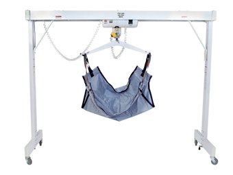
OPERATION OF MECHANISM
|
| 1. |
Fold sling in half lengthwise. (SLANTED POCKETS ARE AT THE TOP OF SLING. USE CHAIN SUPPLIED WITH SLING) |
| 2. |
2. Roll patient away from attendant. |
| 3. |
Place folded sling along length of patient as close to back as possible with lower edge of sling slightly below Knees. |
| 4. |
Roll patient back toward attendant and open sling fully. |
| 5. |
Roll patient back so they are centered along the length of sling. |
| 6. |
Slide one metal sling bar into each pocket of the sling. |
| 7. |
Using the chain, attach the "S" hook into the sling bar. The Opening should face away from the patient. |
| 8. |
Center lift over the patient. |
| 9. |
Lower the spreader bar so that a single chain link can be attached to each side (approximately the 9th link) from the shoulder. Make sure that the spreader bar is inserted into a single chain link. |
| 10. |
When you push the up button, check to ensure patient is seated correctly and is not pitching forward. If patient is pitching forward, return to starting position and make adjustment. |
| 11. |
If patient is positioned properly, continue to raise them to a point that they can be moved across the track and positioned over the chair. |
| 12. |
Lower patient, guiding them into their chair by gently pushing on their knees. |
| 13. |
When patient is seated and chain is slightly slack, detach "S" hooks from metal bar in sling, raise the lift using push button control and send unit off to side. |