|
 |
- Product Overview
- Operational Instructions
- Downloads
- Technical Specifications
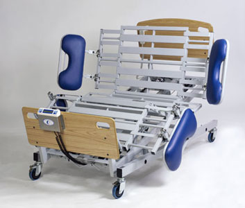
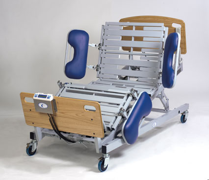
BARIBED 1400CAM.SR - EXPANDABLE BARIATRIC BED
The BARIBED 1400CAM.SR Bariatric Bed is designed primarily for use in Hospitals and other institutions. Its purpose is to support patients whose weight exceeds that of the conventional bed and who may require specialized positioning. The frame is constructed entirely of metal. The frame in its lowest position is approximately 14" from the floor to the mattress pan. In the upper position the height is approximately 29". The unique expandable frame design allows the bed to accommodate 37", 39", 42", 48" or 54" support surfaces. When outfitted with the appropriately designed mattress (39", 42", 48, or "54") you can adjust the bed surface so as to allow it to fit through a 39" door opening. |
 |
The frame is designed to support a safe working load of 1000 lbs. Side rails at the head end are standard. Optionally, the bed can be equipped with foot end side rails and foot and head end side rail pads. The 45 degree angle setting of the side rails assists in patient ingress and egress.
An optional trapeze is capable of supporting the maximum patient weight for this type of bed. Swivel casters 5" in diameter and a hard tread wheel with break and swivel lock provides for easy movement of the bed.
A mattress guard rod across the foot end of the bed prevents the foot end of the mattress from sliding off the bed, particularly when the head end (fowler) is raised. |
 |
The bed contains four electric drive modules, one for the head, one for the knee, one Hi/Lo for head end of the bed and one Hi/Lo for the foot end of the bed. A hand crank is supplied which can be used to adjust the bed in ca'se of power or actuator failure.
- Five Function Operation -A 10 button, 5 function hand pendant is used to control the positioning of the bed.
- The BED up and down buttons causes the bed to raise and lower.
- The HEAD up and down button causes the head of the bed to raise and lower (fowler).
- The KNEE foot buttons cause the knees and lower portion of the legs to be raised and lowered. (The Knee Gatch)
|
|
| |
| KEY PRODUCT FEATURES: |
- Delivered with main frame assembled.
- Can accommodate the widest lateral rotation mattresses.
- Single button cardiac chair position and single button return to supine, for quicker patient access.
- Single button Trendelenburg operation without having the bed either full up or full down. Plus, you will never have to crawl under the bed to flip a Trendelenburg switch. It is emergency situation-ready.
- Steer-Lock and Total-Lock casters positioned for safety, stability and easy maneuverability.
- Optional built-in scale system provides accurate patient weights at the touch of a button, no matter what position the patient or the bed is in. Optional trapeze.
|
| RECEIVING INSTRUCTIONS |
The bed and its accessories may be shipped to you on a pallet. Before opening this pallet, visually inspect the packing carton for any signs of freight damage. If damage is detected, do not accept the shipment without making a notation on the bill of lading, briefly describing the damage, and file a damage complaint with the freight company.
Carefully remove the bed and it's associated parts from the pallet. Inspect these parts to make sure there is no internal damage. If internal damage is noticed, contact the freight company immediately to file a damage claim complaint
Carefully open all packing and verify that all components on the packing slip have been received. If anything is missing, notify the dealer from whom you obtained the bed.
ALL MATERIAL RECEIVED SHOULD BE CHECKED AGAINST THE PACKING LIST TO VERIFY THAT YOU HAVE RECEIVED ALL COMPONENTS IN GOOD CONDITION. |
| |
| |
| GENERAL CAUTIONS AND WARNINGS: |
|
WARNINGS
- Keep all objects out from under the bed. Certain parts under the bed raise and lower when the bed is in motion.
- Do not place arms or head into frame while operating. Stand clear of the bed frame before operating. Make sure there is nothing under the bed to interfere with proper bed operations.
- Make sure the cord from the control module and the cord from the pendant are properly positioned before operating the bed. Do not allow either of these cords to get caught in the moving members of the bed.
- Do not operate this device if the power cord or any of the cords between the control module and the associated parts are cut, frayed or loosely connected.
- Do not service this device without first disconnecting the power cord.
CAUTIONS
- Rotating parts. - Keep fingers and arms clear of bed when mechanism is moving.
- Pinch point. Keep objects away from these areas while bed is in motion.
- Electrical hazard may occur if device is plugged into inadequate power supply. Make sure that the device is plugged into a 115 volt, 3 prong grounded outlet with a capacity of at least 15 amperes.
- The mattress should be sufficiently wide enough to prevent patient body parts from falling between the side rails and the mattress.
- Keep feet clear of casters.
|
| |
| |
| ASSEMBLY INSTRUCTIONS: |
| 1. |
lf the pendant is not already attached to the bed, plug the hand pendant into the control module. Make sure the pendant plug is securely fastened in the
control module. It should snap in place. Fasten the Pendant cord to the frame
using the cable clamp provided. If it becomes necessary to unplug the pendant,
squeeze the little release levers on either side of the plug. Then gently remove
the plug. |
| 2. |
lnstall the headboard posts in the inward most sockets provided at the
head end with the board closet to the mattress. The power cord hanger should
be on the side away from the mattress. |
| 3. |
lnstall the foot board posts in the outward most sockets provided at the
foot end with the board further away from the mattress. |
| 4. |
lf this is a scale model install the readout in the bracket on the foot board. Connect the two leads from the bed to the readout. One cable connector has 6
prongs. The other has 4 prongs. Make sure the cables are connected to the
proper readout connectors. |
| 5. |
Do a careful walk around inspection of the bed. Look underneath the bed
to make sure there is nothing stored there. This area must be kept clear
to avoid any interference with parts motion of the bed which takes place
during the bed operation. |
| 6. |
Plug the power cord into a 115 volt grounded socket having a
capacity of at least 15 amperes. |
| 7. |
Locate the rocker on/off switch on the control module. Make sure the
switch is on and that the switch button is illuminated: |
| 8. |
Using the hand pendant, cycle the bed through all of its operations. Make
sure that everyone including yourself is clear of the bed during these operations. |
| 9. |
When you are satisfied that the bed is operating properly, instruct all
personnel who may be involved in the bed operation. Once you have become
comfortable with the operation of the be as specified in the Operation Manual,
instruct all personnel who may be involved in the bed operation . |
| |
| |
| ADJUSTING BED WIDTH: |
|
The bed standard adjustable widths are 3T', 39", 42", 48", and 54". (Bed may be special ordered with stops located any where between 3T' and 54").
There are four adjustable sections along each side.
- A) Fowler
- B) Center section
- C) Upper Knee Gatch
- D) Lower Knee Gatch
Each section adjust individually by pulling down on the locking pin ring "A", located approximately at the center of each section, and sliding the Mattress Support in or out as required (see drawings below).
NOTE: Slight inward pressure on the section to be adjusted may be required in order to disengage the locking pin.
- 1- Raise bed to full up position.
- 2- Pull the ring @ down (It will move about 1/2").
- 3- Move the ADJUSTABLE SECTION in the desired direction.
- 4- Release the pin.
- 5- Continue to move ADJUSTABLE SECTION until pin snaps into desired locking hole.
|
 |
| |
| |
| CLEANING AND MAINTENANCE: |
CLEANING
Before cleaning any portion of the bed, disconnect the power cord from the wall outlet.
- 1. Using standard cleaning procedures, wipe down.the frame of the bed. Be sure to wear appropriate protection for the type of materials used to clean the bed.
- 2. Use cleaning detergents sparingly around the pendant controller, the electronic controller and the motors.
PERIODIC INSPECTION AND MAINTENANCE
The amount of maintenance required by the bed will be dictated by its use. As a minimum the unit should be periodically inspected every 6 months.
- 1.After a week or two of usage, check all the bolts to be sure t~at none of them have worked loose and that all pins are in their normal location and securely fastened. Check all welds.
- 2. At least once every 6 months the actuator drive screw should be lubricated using a heavy duty grease such as Drydene #5871 or equivalent.
- 3. Put light machine oil on all pivot points every 6 months.
- 4. Check all electrical connections for tightness.
- 5.Check alt electrical wiring for fraying, kinking and or deterioration.
IF ANY DISCREPANCIES ARE NOTED DURING INSPECTION THEY MUST BE CORRECTED BEFORE CONTINUED USE OF THE BED.
|
|
| 
|
| TECHNICAL SPECIFICATIONS |
| Weight Capacity: |
1000 lbs. |
| Overall Width: |
39.5 inches, expandable to 56.5 inches |
| Overall Length: |
89 inches |
| Mattress Pan Mattress pan width adjustable: |
37”, 39 “, 42", 48”, 54” |
| Overall length: |
80”; optional 10” removable extension |
| Height: |
Lowest position: 16” |
| Mattress Pan to Floor Highest position: |
30” (add mattress height for overall height) |
|
| |
|
| Functions: |
|
Head/Fowler:
Foot/Knee Catch:
Bed Hi/Lo:
Trendelenburg:
Reverse Trendelenburg:
Cardiac Chair Function:
|
adjustable up to 70 degrees
adjustable up to 40 degrees
adjustable up to 12 degrees
adjustable up to 12 degrees
mattress pan height adjustable from 16” to 30”
One button function or manual crank |
Seat Up: |
Raises Fowler 82 degrees to floor
Raises Knee Catch
Raises Bed Head End
Lowers Bed Foot End |
Seat Down: |
Lowers all functions to supine
Bed Height to lowest position |
Casters: |
Diameter: 5”
Width: 1.25”
Brakes: Total Lock (Brake and Swivel)
Tread: Non-marring
Mounting locations: Stem mount to corners of fixed base |
Headboard |
18” x 38” x .75” (Removable, no tools required)
Two hand grip openings |
Foot board |
15” x 38” x .75” (Removable, no tools required)
Two hand grip openings |
Side Rails |
Head end standard, 3 position swing type; Foot end optional |
|
|
|